An electrolyte with phosphate bonded perchloric (PBP) superstructure is proposed to simultaneously boost cathodic Na⁺ transport and promote the formation of a robust Na₄P₂O₆/Na₄P₂O₇ interphase on the anode surface. The PBP superstructure interacts with free water molecules, reducing their activity, and meanwhile, it promotes the formation of a stable, uniform, and robust solid electrolyte interphase (SEI) on the anode surface. This electrolyte design enables batteries to deliver a cathodic specific capacity of 198.21 mAh g⁻¹ at 50 mA g⁻¹, with prolonged operating time exceeding 1440 h and an energy density of 82.31 Wh kg⁻¹ (based on the mass of electrode materials). Furthermore, the electrolyte demonstrated an expanded electrochemical stability window (ESW) of ≈3.2 V and exceptional low-temperature performance, enabling stable battery operation at −20 °C with a specific capacity of 82.91 mAh g⁻¹. The study underscores the potential of PBP superstructure as an alternative electrolyte engineering pathway toward energy-dense and long lifespan aqueous sodium-ion batteries (ASIBs). The findings were published in Advanced Materials under the title “Phosphate Bonded Perchloric Superstructure Enables Energy-Dense and Ultra-Stable Aqueous Sodium-Ion Batteries.” The corresponding authors are Prof. Pu Chen of Eastern Institute of Technology, Ningbo, Prof. Guohui Li of Liaoning Normal University, and Dr. Jian Zhi of the Shanghai Institute of Ceramics, Chinese Academy of Sciences.
Article Highlights:
1. An innovative electrolyte design strategy based on a “phosphate-bonded perchloric (PBP) superstructure.”
The researchers developed a phosphate-bonded perchloric (PBP) electrolyte superstructure (NaClO₄–trimethyl phosphate (TMP)–H₂O) that synergistically benefits both electrodes. On the cathode side, compared to a pure aqueous electrolyte, the Na⁺ ions in the electrolyte with PBP superstructure exhibit higher free energy. This makes them less stable and facilitates easier intercalation and de-intercalation within the cathode material, resulting in a higher charge/discharge specific capacity. Furthermore, the PBP superstructure interacts with free water molecules, reducing their activity, and meanwhile, it promotes the formation of a stable, uniform, and robust SEI on the anode surface. This SEI layer not only facilitates the rapid transport of Na⁺ ions but also effectively mitigates parasitic side reactions, significantly enhancing the cycling stability of the batteries.
2. Phase-transition mechanism and reversible reaction pathway of the NaMnO₂ cathode in aqueous electrolytes.
The results show that, for the NaMnO₂ cathode in aqueous electrolytes, the material directly involved in the electrochemical reaction is not NaMnO₂ itself. During the first charging process, NaMnO₂ undergoes a phase transition, transforming into Na₄Mn₁₄O₂₇·9H₂O as sodium ions are gradually de-intercalated to form Mn₇O₁₃·5H₂O. During the subsequent discharging process, sodium ions re-intercalate, converting the material back to Na₄Mn₁₄O₂₇·9H₂O. This interconversion between Mn₇O₁₃·5H₂O and Na₄Mn₁₄O₂₇·9H₂O continues through the following cycling process. The PBP superstructure promotes complete de-intercalation of sodium ions during charging and smoother sodium-ion intercalation during discharging, thereby providing higher capacity.
3. In-situ construction of a highly stable and Na⁺-conductive solid electrolyte interphase (SEI).
The electrolyte with PBP superstructure promotes the formation of a stable, uniform, and robust SEI layer on the anode surface. ToF-SIMS analysis indicates that the chemical composition of the SEI layer includes Na₄P₂O₆ and Na₄P₂O₇; these compounds are sodium-ion conductors, which explains their suitability as SEI components for sodium-ion battery anodes. The stable, uniform, and robust coverage of the SEI layer more effectively isolates the electrode material from the electrolyte, thereby significantly mitigating parasitic side reactions. The resulting full battery demonstrates operating time exceeding 1440 h and maintains excellent electrochemical performance at −20 °C and under high-mass-loading conditions.
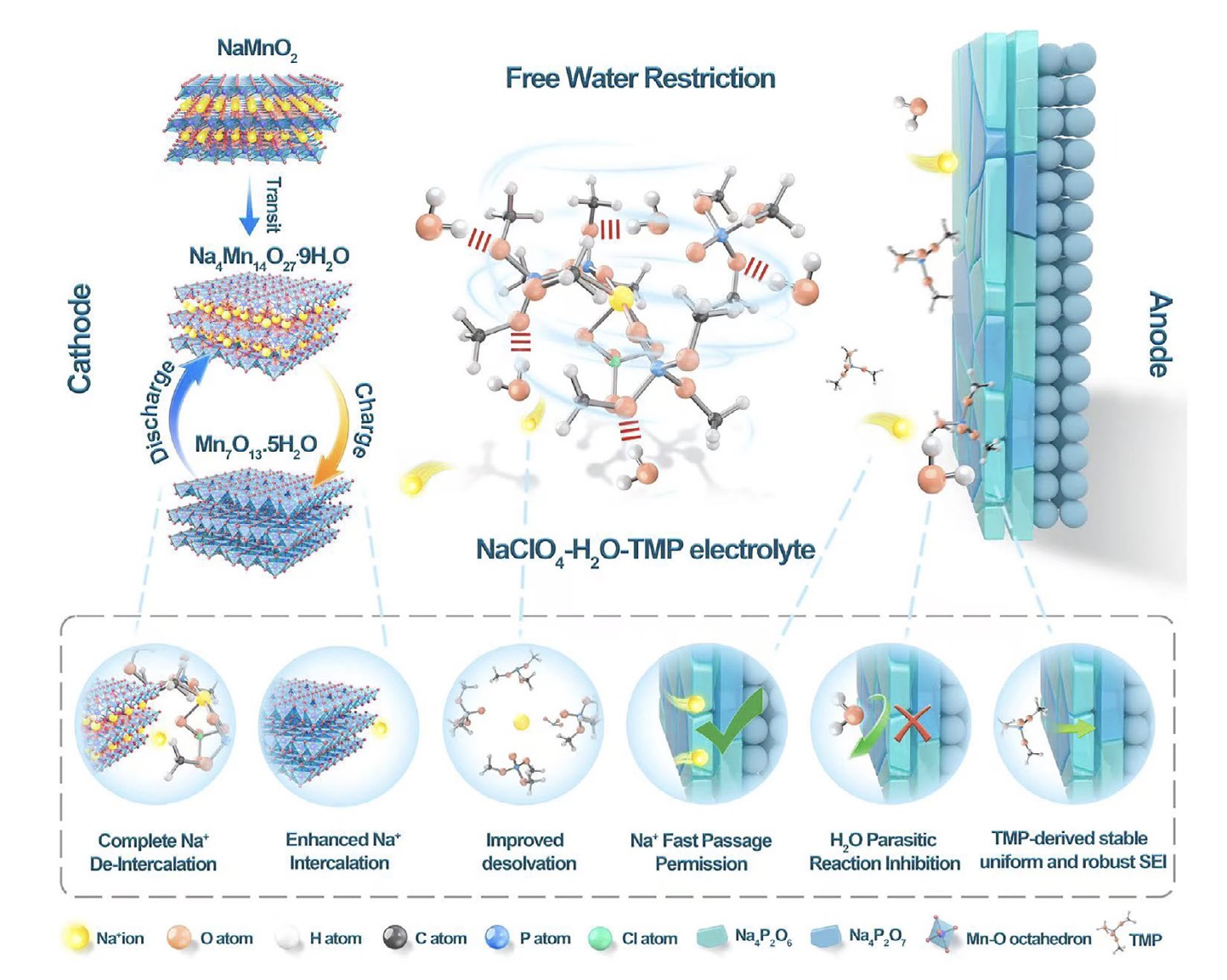
Figure 1. Overall mechanism and functions illustration diagram.
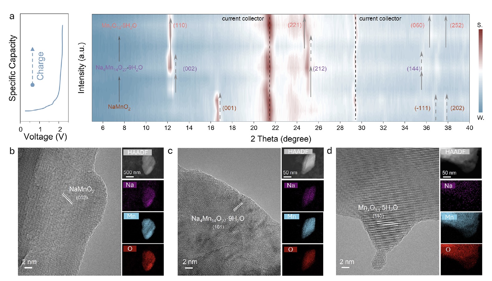
Figure 2. Characterization of cathode evolution. a) Ex situ XRD contour plots of cathode materials during the initial charging process. b) HR-TEM image and elemental mapping of fresh NaMnO₂ cathode material. c) HR-TEM image and elemental mapping of cathode material after transition. d) HR-TEM image and elemental mapping of the fully charged state cathode material.
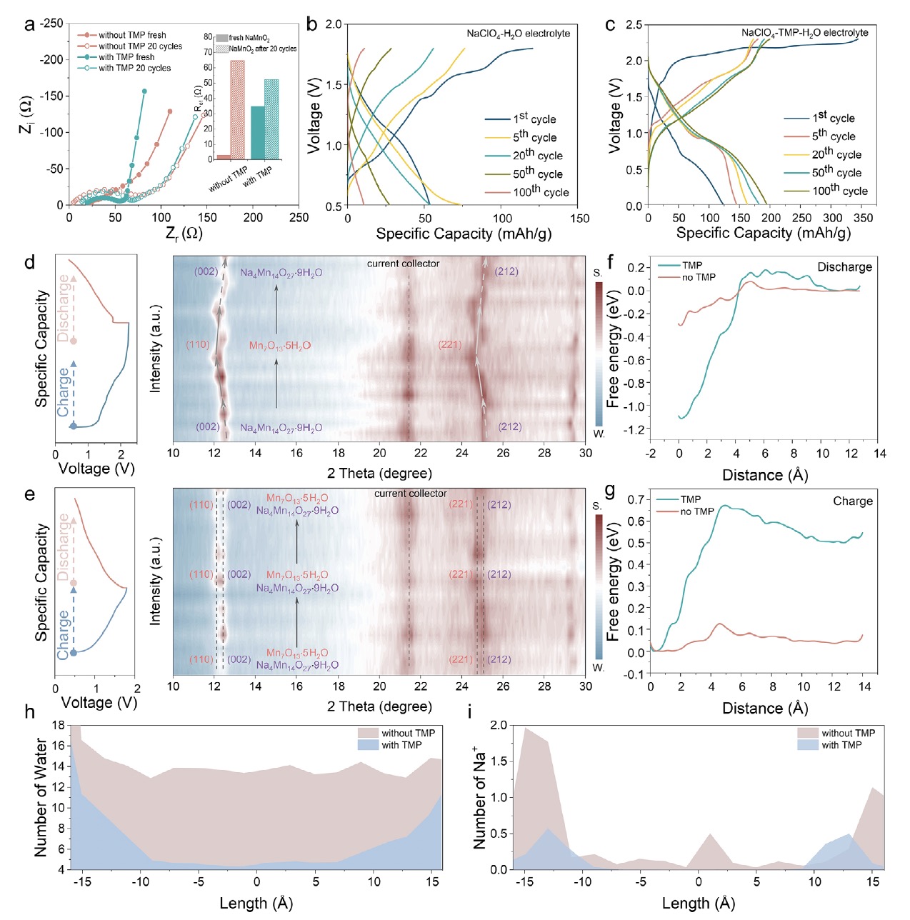
Figure 3. Analysis of the role of NaClO₄–TMP–H₂O electrolyte on the cathode. a) EIS of NaMnO₂ cathode before/after cycles in the electrolytes with/without TMP. (Inset: Comparison of Rct of NaMnO₂ cathode before and after cycling in electrolytes with and without TMP.) b) Charging and discharging curves of batteries using NaClO₄–TMP–H₂O electrolyte. c) Charging and discharging curves of batteries using NaClO₄–H₂O electrolyte. d) Ex situ XRD contour plots of cathode materials during charge and discharge using NaClO₄–TMP–H₂O electrolyte. e) Ex situ XRD contour plots of cathode materials during charge and discharge using NaClO₄–H₂O electrolyte. f) Free-energy profile of the intercalation (discharge) process. g) Free-energy profile of the de-intercalation (charge) process. h) Number of water molecules present in the cathode. i) Number of sodium ions present in the cathode.
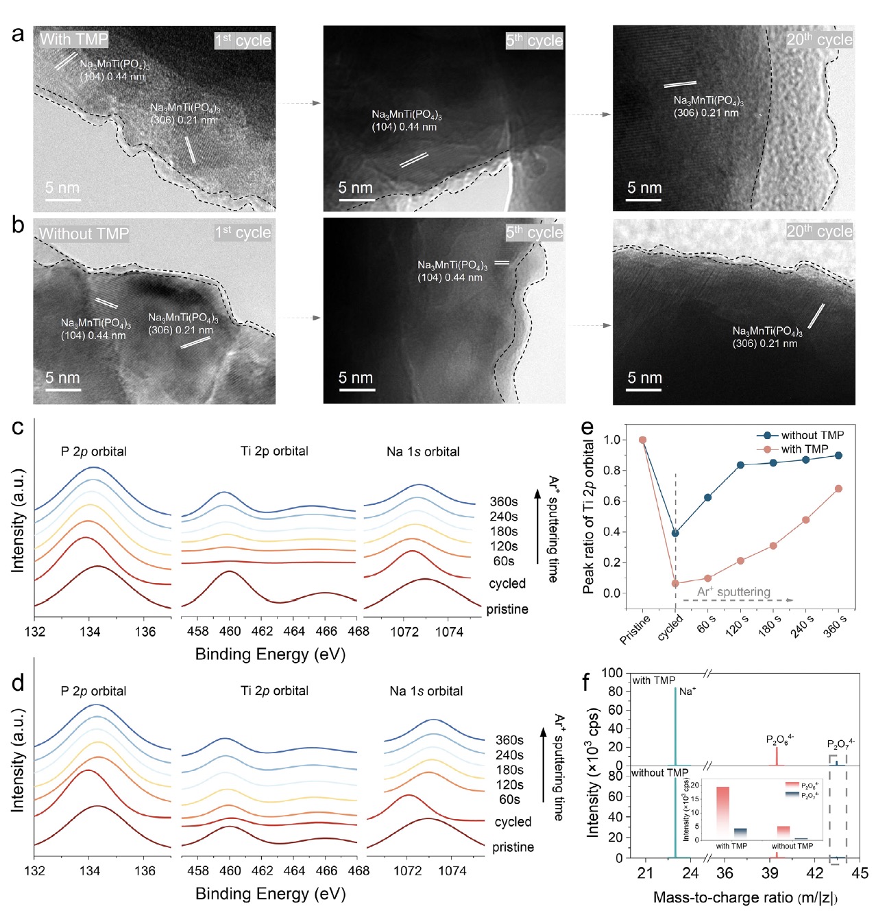
Figure 4. Analysis of the role of NaClO₄–TMP–H₂O electrolyte on the anode. a) HR-TEM images of NMTP after cycling for 1, 5, and 20 cycles in NaClO₄–TMP–H₂O electrolyte. b) HR-TEM images of NMTP after cycling for 1, 5, and 20 cycles in NaClO₄–H₂O aqueous electrolyte. c) XPS spectra with Ar⁺ sputtering of the anode using NaClO₄–TMP–H₂O electrolyte. d) XPS spectra with Ar⁺ sputtering of the anode using NaClO₄–H₂O aqueous electrolyte. e) Peak ratio of the Ti 2p orbital in NaClO₄–TMP–H₂O electrolyte and NaClO₄–H₂O aqueous electrolyte. f) ToF-SIMS spectra of anodes cycled in NaClO₄–TMP–H₂O electrolyte and NaClO₄–H₂O aqueous electrolyte. (Inset: Intensities of P₂O₆⁴⁻ and P₂O₇⁴⁻.)
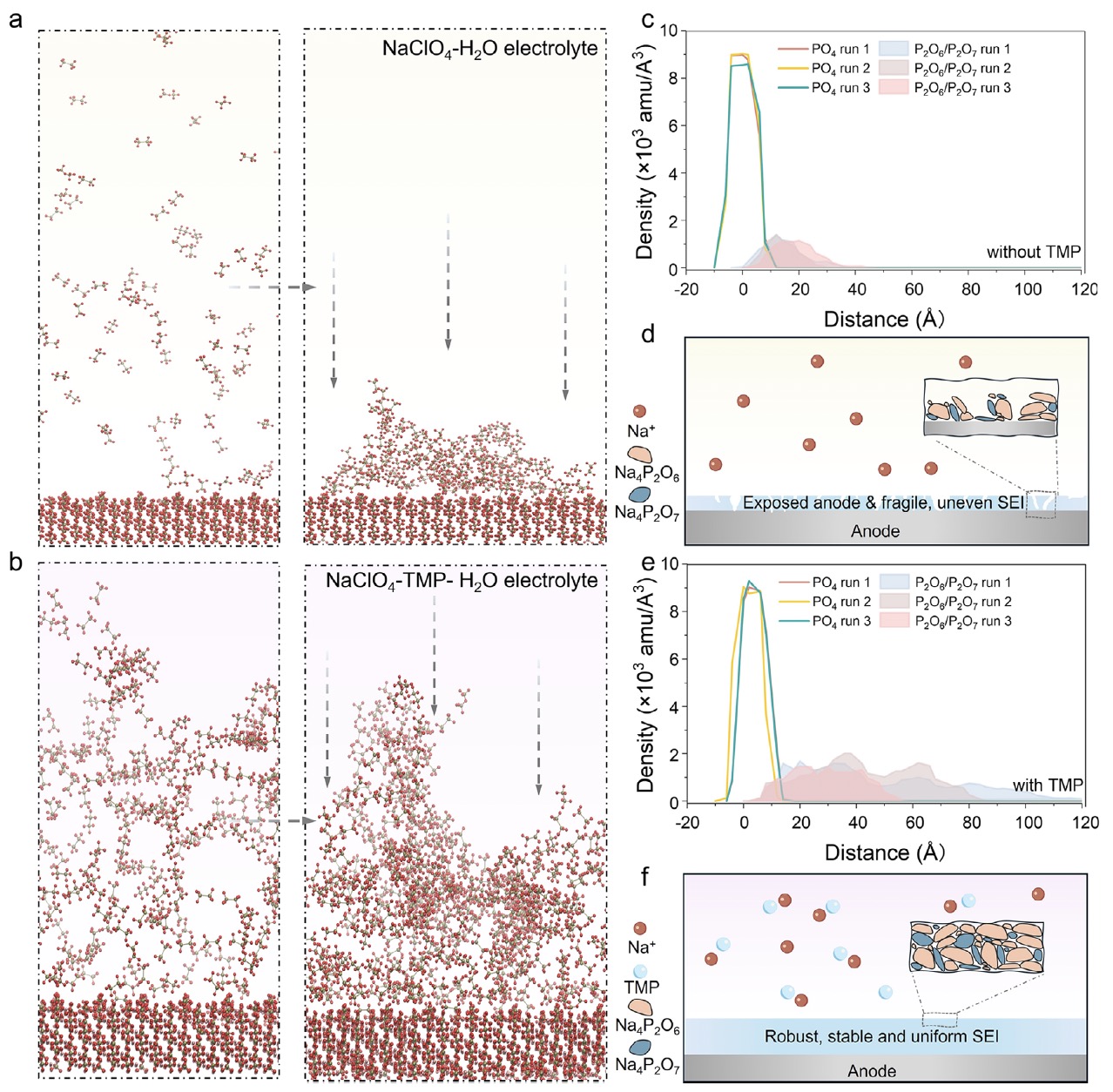
Figure 5. Computational simulations comparison of SEI. a) Left: The initial snapshot of P₂O₆⁴⁻ and P₂O₇⁴⁻ in NaClO₄–H₂O aqueous electrolyte; right: The aggregation snapshot of SEI on the anode in NaClO₄–H₂O aqueous electrolyte. b) Left: The initial snapshot of P₂O₆⁴⁻ and P₂O₇⁴⁻ in NaClO₄–TMP–H₂O electrolyte; right: The aggregation snapshot of SEI on the anode in NaClO₄–TMP–H₂O electrolyte. c) The mass densities projected onto the axis perpendicular to the anode surface in NaClO₄–H₂O aqueous electrolyte. d) Schematic diagram of SEI in NaClO₄–H₂O aqueous electrolyte. e) The mass densities projected onto the axis perpendicular to the anode surface in NaClO₄–TMP–H₂O electrolyte. f) Schematic diagram of SEI in NaClO₄–TMP–H₂O electrolyte.
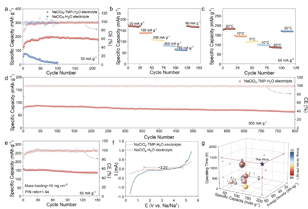
Figure 6. Electrochemical performance tests. a) Comparison of the cycling performance of the NaMnO₂/NTP full cell using NaClO₄–TMP–H₂O electrolyte and that using NaClO₄–H₂O aqueous electrolyte at 50 mA g⁻¹ at room temperature. b) Rate performance of the NaMnO₂/NTP full cell using NaClO₄–TMP–H₂O electrolyte at room temperature. c) Low-temperature performance of the NaMnO₂/NTP full cell using NaClO₄–TMP–H₂O electrolyte. d) Cycling performance of the NaMnO₂/NTP full cell using NaClO₄–TMP–H₂O electrolyte at 500 mA g⁻¹ at room temperature. e) Cycling performance of the NaMnO₂/NTP iron-plate battery with high mass loading and an N/P ratio of 1.44 using NaClO₄–TMP–H₂O electrolyte at room temperature. f) Comparison of ESW between NaClO₄–TMP–H₂O electrolyte and NaClO₄–H₂O aqueous electrolyte. g) Comparison of specific capacity, energy density, and operating time among this work and state-of-the-art ASIBs.
Article Conclusion:
In this study, the researchers systematically investigate the energy-storage mechanism of the NaMnO₂ cathode for ASIBs and report a novel interfacial chemistry for the anode. Based on this intercalation and interfacial chemistry, a PBP electrolyte superstructure is introduced, enabling simultaneous effects on both the cathode and anode sides. On the cathode side, the Na⁺ ions in the electrolyte with PBP superstructure possess higher free energy, leading to greater instability, facilitating their intercalation into and de-intercalation from the cathode material, thereby enhancing the specific capacity. On the anode side, the electrolyte with PBP superstructure promotes the formation of a stable, uniform, and robust SEI layer, effectively reducing parasitic side reactions and improving cycling stability. The assembled full battery demonstrates a high specific capacity of 198.21 mAh g⁻¹, operating time exceeding 1440 h, and an energy density reaching 82.31 Wh kg⁻¹ based on the mass of active electrode material. Furthermore, such an electrolyte with a PBP superstructure offers excellent low-temperature performance, maintaining normal operation and a specific capacity of 82.91 mAh g⁻¹ at −20 °C. This study provides new perspectives on the intercalation and interfacial chemistry of ASIBs and proposes an innovative electrolyte design strategy for the development of high-performance ASIBs.
Article Link:
https://doi.org/10.1002/adma.202513415